
 |
Eager Space | Videos by Alpha | Videos by Date | All Video Text | Support | Community | About |
|---|
Thermal Management in Space - Abraham Hertzberg
https://www.nss.org/settlement/nasa/spaceresvol2/thermalmanagement.html
Defense systems information analysis center
https://dsiac.dtic.mil/articles/space-travel-aided-by-plasma-thrusters-past-present-and-future/
Electric propulsion needs by OHB
https://www.researchgate.net/publication/330082426_OHB-System's_View_on_Electric_Propulsion_Needs
VISIMR VX-200 Performance and new-term SEP capability for unmanned mars flight
https://web.archive.org/web/20110311141639/http://spirit.as.utexas.edu/%7Efiso/telecon/Glover_1-19-11/Glover_1-19-11.pdf
Megawatt class nuclear space power systems, multiple volumes:
https://ntrs.nasa.gov/search?q=megawatt%20class%20nuclear%20space%20power&page=%7B%22from%22:0,%22size%22:25%7D
NASA Nuclear electric propulsion for 2033 mars roundtrip
https://www.researchgate.net/publication/237827299_Use_of_High-Power_Brayton_Nuclear_Electric_Propulsion_NEP_for_a_2033_Mars_Round-Trip_Mission/link/00b495318c2dba70a4000000/download
NASA Compass NEP - Chemical Hybrid
https://ntrs.nasa.gov/api/citations/20210017131/downloads/TM-20210017131_errata.pdf
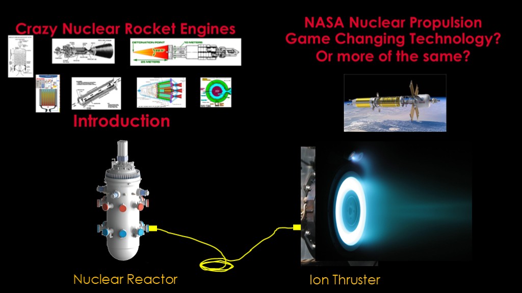
If you've watched my videos on nuclear rocket engines, you know that I think most of them are crazy, with the possible exclusion of nuclear thermal designs, which would definitely work but aren't very exciting.
There's another approach that still uses nuclear fission but not directly in the engine.
You take a small nuclear reactor, plug it into an ion thruster, turn the ion thruster on and you have a nuclear electric propulsion system.
NEP is getting a lot of press these days. Just how promising is it?
To start, we'll need to understand a bit about rocket engines.
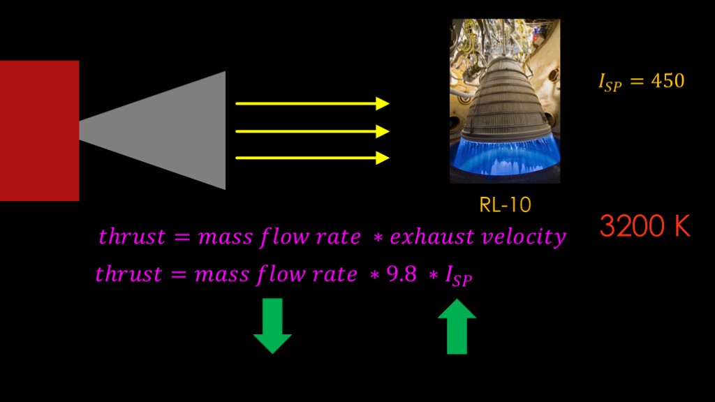
Rocket engines work by throwing mass out of the rocket nozzle. The amount of thrust you get is equal to the amount of mass you throw out multiplied by how fast you throw it, otherwise known as the exhaust velocity.
That would often be written using the specific impulse rather than the exhaust velocity.
You want the highest possible specific impulse so that you use less mass for a given amount of thrust. Less mass devoted to propellant means more mass devoted to payload.
The classic RL-10 engine is one of the most efficient chemical engines around, with a specific impulse of around 450.
To get higher specific impulse you need to run your engine hotter, but the RL-10 is already running at a temperature of about 3200 kelvin, and you can't go much hotter than that without melting the engine.
What we need is a way to accelerate our propellant atoms without using a rocket engine that is temperature limited.
This is not a new idea.
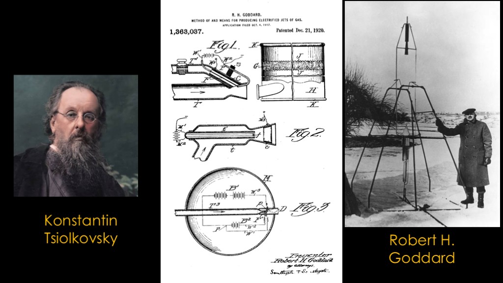
Kontantin Tsiolkovsky appears to have come up with it about the same time as liquid fueled rocket pioneer Robert H. Goddard. Goddard got his approach patented, way back in 1920, in a patent titled "Method of and means for producing electrified jets of gas"
The concept is pretty simple.
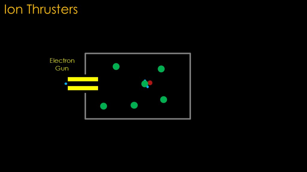
We introduce our propellant into an ion generation chamber. Electrons are introduced into the chamber through an electron gun, and the electrons collide with the propellant atoms, knocking electrons off of them and leaving those atoms with fewer electrons than normal and therefore a positive charge. We call these positive ions.
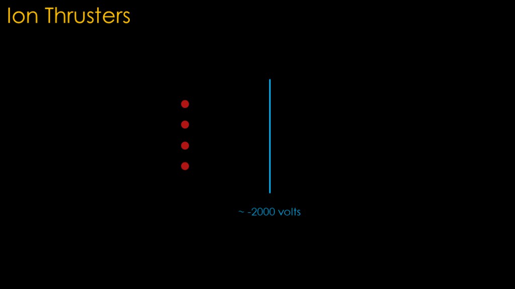
Now we have a bunch of positive ions floating in our propellant gas.
If we put a plate near those ions and put a negative voltage on it - something around a few thousand volts - we will create an electrical field and the ions will be strongly accelerated towards the negative plate and thwack into it.
That might be useful for physics experiments, but it's not a very good rocket engine because it has no exhaust.
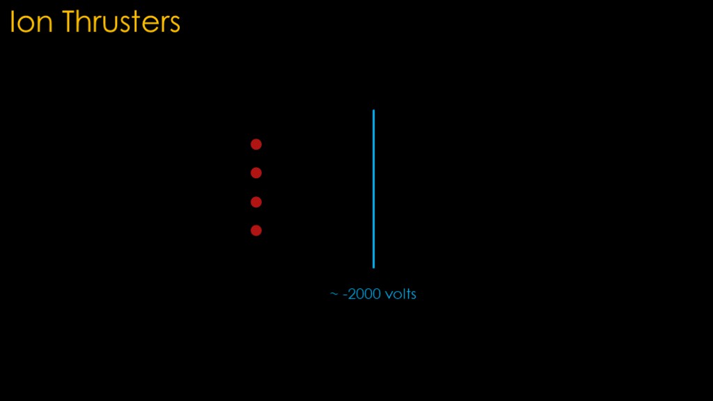
What if we make some holes in the plate?
The holes let some of the ions make it through and out into space, so we have a rocket engine.
But the other ions are going to hit the structure of the plate and quickly damage it.
What we need is a way to guide the ions so they will go through the holes.
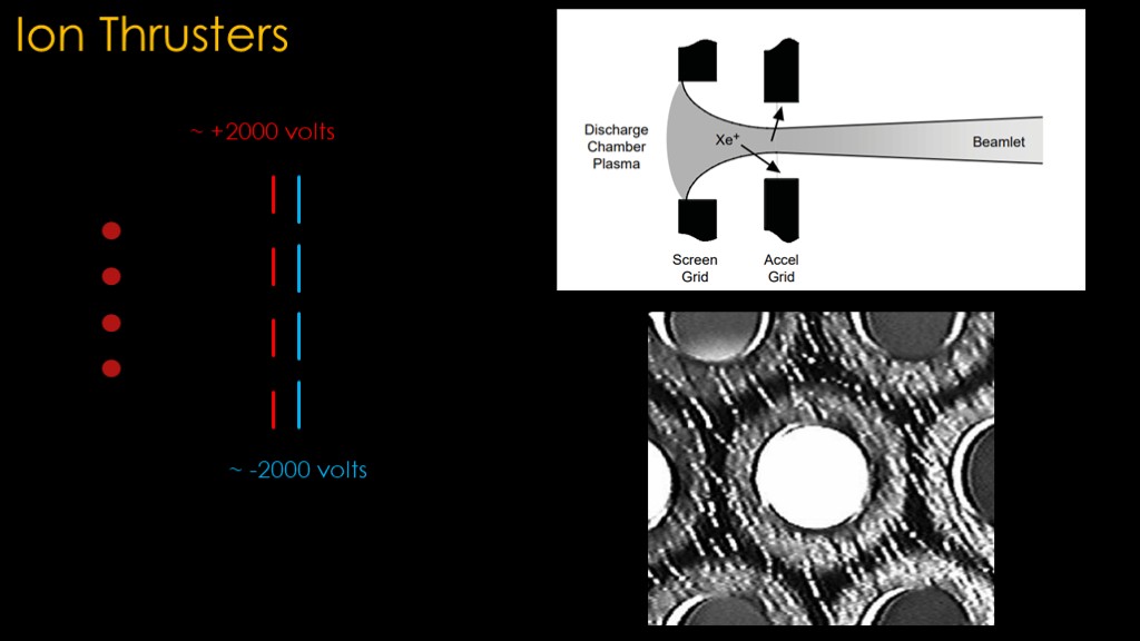
The solution is to add a second, positively charged plate, one with bigger holes. The holes are sized so the ions can still be attracted to the negative plate but the positive plate charge ensures they only go through holes, which are aligned with the negative plate holes, and the ions therefore make it through the holes.
Here's a nice diagram of how it works; the positive plate is known as the screen grid, and the negative one is called the accel grid. What is actually used is a plate with hexagonal holes in it - it looks like this.
Ion thrusters are great.
Not only do they look really cool, they can accelerate their fuel atoms to very high speeds, yielding high specific impulse and very economical fuel usage.
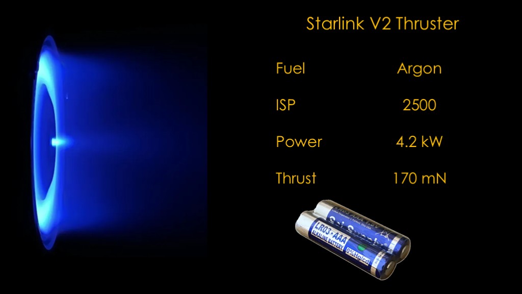
The starlink version 2 thruster uses Argon as a fuel and has a specific impulse of 2500, or over 5 times that of the best chemical rockets.
That is great.
The problem is that accelerating the ions requires power. With chemical rockets that comes from the chemical reaction between propellants, but since ion thrusters don't use chemical reactions, they need electrical power.
This thruster can use 4.2 kilowatts of power, and from that power, it will generate 170 millinewtons of thrust. That's roughly equivalent to the weight of two triple A batteries.
This low thrust has limited the use of the ion thrusters, but there is one application where they dominate.
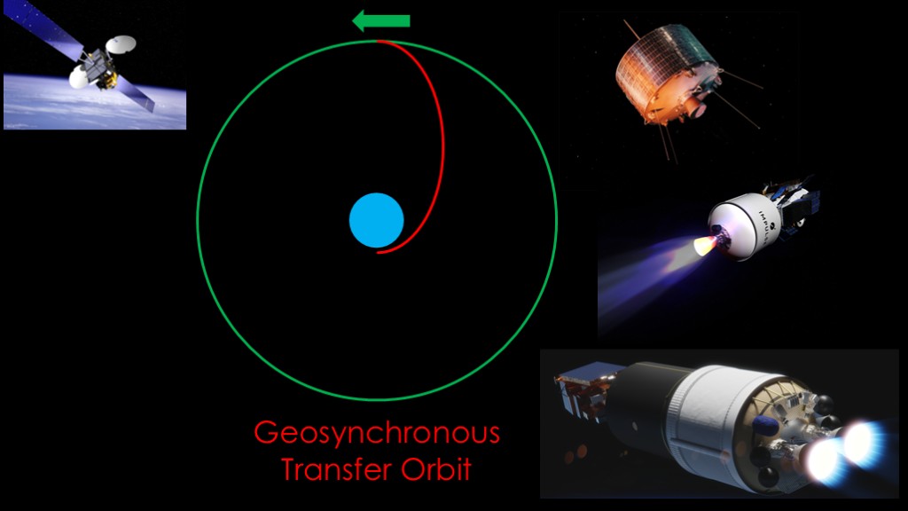
That application is geosynchronous communication satellites.
The target orbit is a very high orbit. The most efficient way to get there is to start with an elliptical geosynchronous transfer orbit, where the coasts all the way out to geosynchronous orbital distance, and then a rocket engine is used to circularize the orbit.
That might be done with a thruster that is part of the satellite, it might be done with a dedicated kick stage, or it might be done with a rocket second stage. Any Vulcan or Falcon 9 missions for the department of defense that involve long coast times are generally doing this.
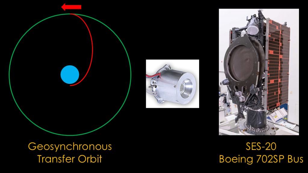
As ion thrusters got practical, they were first adapted for stationkeeping - small movements to keep the satellite in the proper location - and then ultimately they were adapted to replace the chemical thrusters used to place the satellites in the proper orbit.
That was the advent of the "all electric" communications satellite, such as the SES-20 built on the Boeing 702SP satellite bus. All electric is a bit of a misnomer because the ion thrusters still require a fuel.
Communications satellites are uniquely suited to this application because they have large solar panels to provide power for communications, so no additional power source is required for ion thrusters...
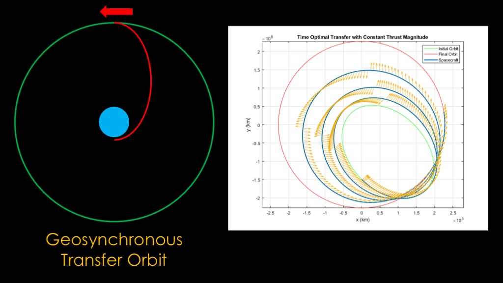
That is, at least, if you are willing to wait 6 to 9 months for your satellite to get into the final position, following a very long spiral trajectory. The answer to that question has generally been *yes*, though some customers will pay for a launch vehicle that can put them closer to the target orbit so they can begin operations earlier.
If we want to replace chemical rockets with ion thrusters for missions that require more thrust, we need more power.
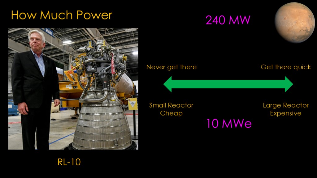
If we are going to replace the chemical combustion that powers this RL-10 with electrical power, we'll need to figure out how much electrical power we will need. The answer is about 240 megawatts.
Chemical combustion is very good at creating immense amounts of power, but the RL-10 is a second stage engine and when getting into orbit you need a lot of thrust to get their quickly and avoid gravity losses. Once you are in orbit, you can get away with much lower thrust levels, as shown by the communication satellite example.
We have a tradeoff. If we want to go to Mars, we can build a small reactor that is cheap, or we can build a larger reactor that is expensive.
That would argue for small and cheap, but if we take that route, we will never get there, or at least not in a reasonable amount of time. A big reactor will get us there quick.
Practical designs seem to be in the megawatt range, and I'm going to use 10 megawatts, with the "e" suffix meaning we need to megawatts of electricity.
You may be asking yourself if we can get this power from solar arrays, and the answer is yes, but that would be another video.
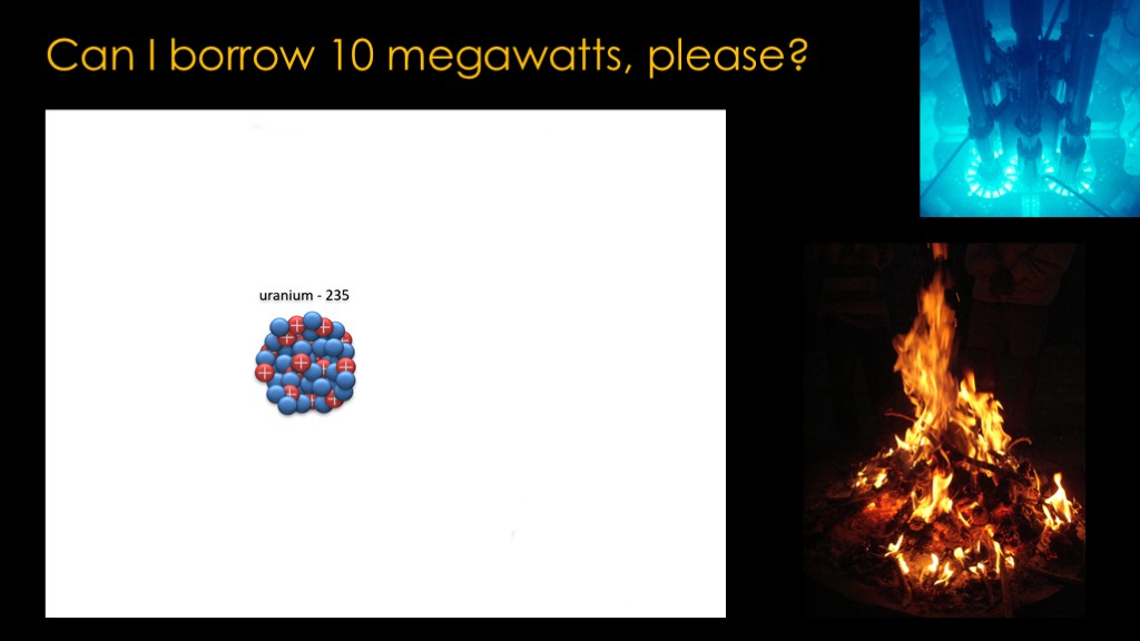
Nuclear reactions are fairly straightforward.
A neutron hits a uranium 235 atom and causes it to break apart into fission fragments, 3 neutrons, and energy in the form of gamma rays. Those fission fragments may also break down themselves.
The first problem is that there's nothing electrical going on. The fission fragments have a lot of velocity but they soon hit other atoms and that velocity is converted to heat, as is the kinetic energy of the neutrons and the energy in the gamma rays.
You have this fancy nuclear reaction thing and all you get out of it heat, the same as you would get from a camp filre.
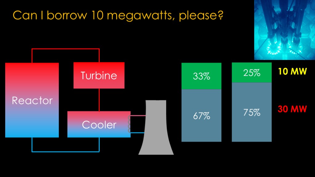
The reactor's job is taking cold working fluid - whatever is used to transfer heat - and heating it up to a high temperature. That working fluid is then piped to a turbine, which extracts energy from the hot working fluid and turns a generator to create electricity.
For the turbine to work, there has to be a place for the working fluid to go after the turbine, and that is the job of a cooler. It removes heat from the working fluid to make it colder and denser. Generally speaking, the higher the inlet temperature and pressure of the turbine and the lower the outlet temperature and pressure of the turbine, the more power you get out.
The cooled working fluid then circulates back into that reactor.
The cooler needs a way to get rid of the heat, and in terrestrial power plants, that is done with some cooling coils in the cooler that circulate cold water. That water is then cooled off in one of the iconic cooling towers.
What this means is that only some of the heat from the reactor goes to turning the turbine to create electricity; the rest has to be taken away by the cooling system.
A typical nuclear power plant will convert 33% of the heat energy into electricity and the remaining 67% will be released into the environment.
Space reactors need to be simple and light and are probably going to be in the 20-30% efficiency range.
That means that to get 10 megawatts of electricity. we are going to have to somehow get rid of 30 megawatts of heat.
It's once again a problem with heat.
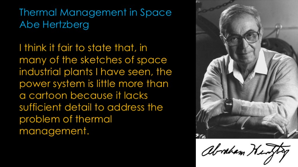
Noted University of Washington Professor Abe Hertzberg wrote the following when discussing thermal management in space
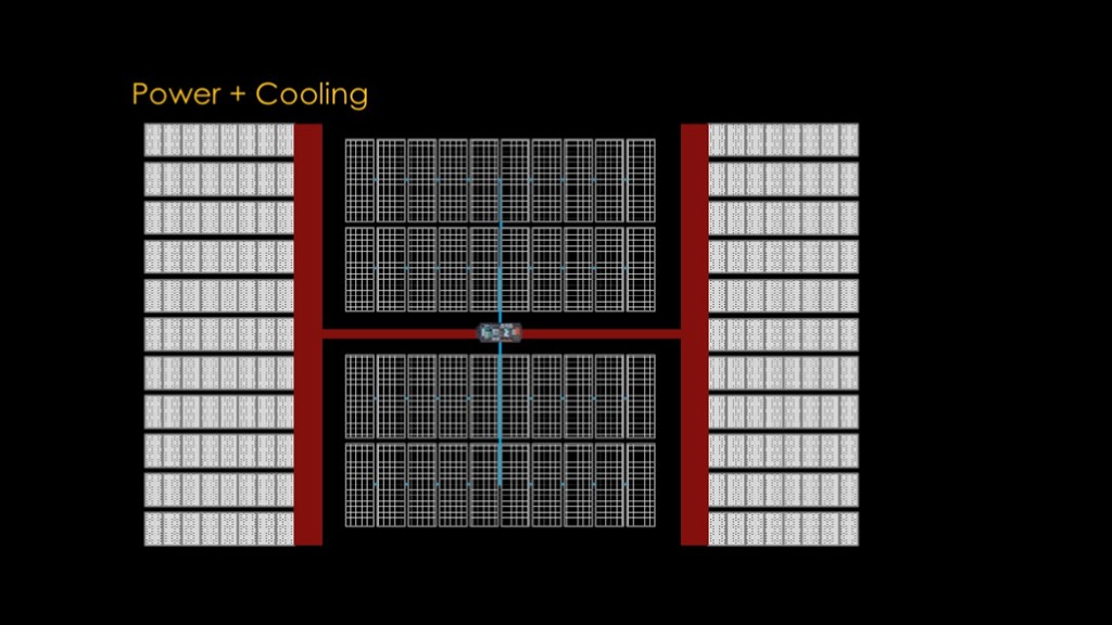
Those of you who have watched my orbital data center video remember that we needed huge radiators to get rid of a puny 250 kilowatts, and that would seem to make our problem hopeless.
30 MW / 250 KW is a very big number, a radiator 120 times this size.
But we aren't cooling a bunch of fairly cool servers, we are cooling a very hot nuclear reactor.
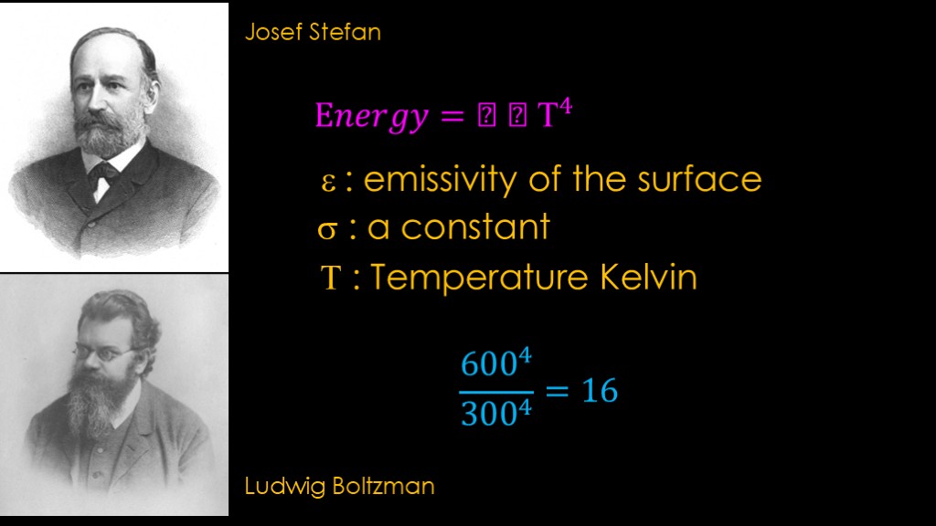
It turns out that higher temperatures make things much better.
Stefan and Boltzman figured this out and came up with what is known as the Stefan Boltzman equation, back in the late 1800s.
The amount of energy a surface can radiate is equal to the emissivity of the surface - how good it is getting rid of energy - multiplied by a constant and multiplied by the temperature in Kelvin raised to the 4th power.
It's that "to the 4th power" part we care about. If we could double the temperature from 300 kelvin to 600 kelvin, our radiator would emit 16 times the energy.
Or, to put it another way, going from 300 kelvin to 600 kelvin would reduce the required radiator area by a factor of 16.
That might just make this practical.
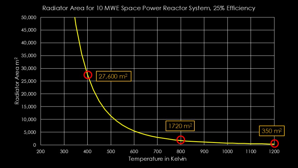
Here's a nice little chart for a space reactor producing 10 megawatts of electricity at 25% efficiency.
The x axis is the temperature in Kelvin, and the vertical axis is the radiator area in square meters.
If our radiator temperature is 400 kelvin, we will need 27,600 square meters to dissipate the energy we need to get rid of, or a square array 160 meters on each side. Doubling that to 800 kelvin reduces the area to 1720 square meters, only 40 meters on a side.
And if we could push it to 1200 kelvin, that require 350 square meters, only 19 meters on a side.
We clearly want a system that uses the highest practical temperatures.
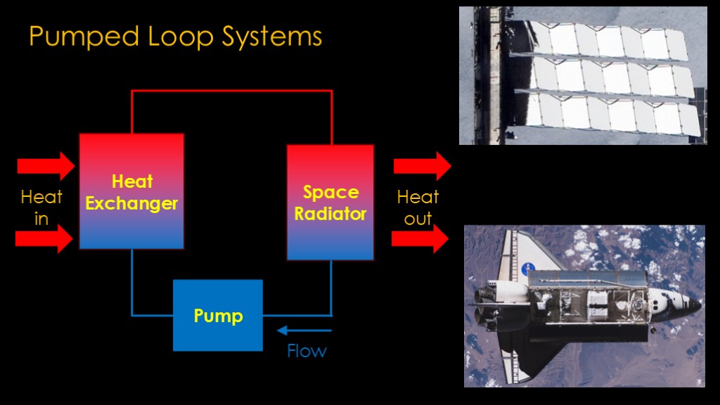
The first approach that comes to mind is a pumped loop system
A system using pumps is very simple; you have a heat exchanger to take the heat and put it into the fluid we are using, a space radiator to get rid of the heat, and a pump to keep things moving. The ISS uses this approach, and the space shuttle used this approach with radiators inside the payload doors.
How would that work in our reactor scenario?
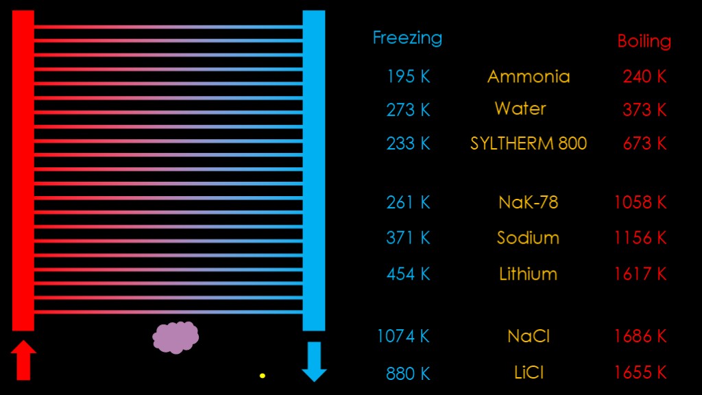
Our radiators are composed of very thin tubes - and perhaps fins - to work effectively. We need to use a coolant that works at the temperatures that we want to use.
Ammonia and water are used on the international space station, but their maximum temperature isn't very high. Dow chemical makes a product called syltherm 800 that goes from 233 kelvin all the way up to 673 kelvin. A bit pricey at over $50 a gallon, but definitely an option.
At those temperatures we would still need over 4000 square meters of radiator area. What we really want is higher temperatures than that so we can make our radiators smaller...
We'll need a coolant that is liquid at much higher temperatures.
That takes us to the alkali metals, including sodium, potassium, cesium, and lithium. An alloy of sodium and potassium known as nak-78 has a nice low freezing point and a relatively high boiling point, but it's not as hot as we would like it to be.
These alkali metals have the small downside that they catch fire or explode when exposed to water or air.
And last, we have metallic salts like sodium chloride and lithium chloride. They have great boiling points but high freezing points as well.
There are two main issues with using metals or metallic salts as coolants.
The first is that they freeze - or solidify - at relatively high temperatures. If you lose your hot input flow - either because you shut the reactor down or you have a fault - there is no more heat input but the radiator will keep doing its job of radiating away heat, and the coolant will solidify in the tubes. At that point your radiator is purely decorative. And you can't melt it out because the radiator is better at radiating heat away than at conducting heat through the cooling channels. This also may be an issue when you are starting the system up.
A second issue is that those thin tubes can be damaged by micrometeroids, at which point your radiator starts venting fluid into space.
Not good. Are there alternatives?
NASA has a number that they call "advanced concepts".
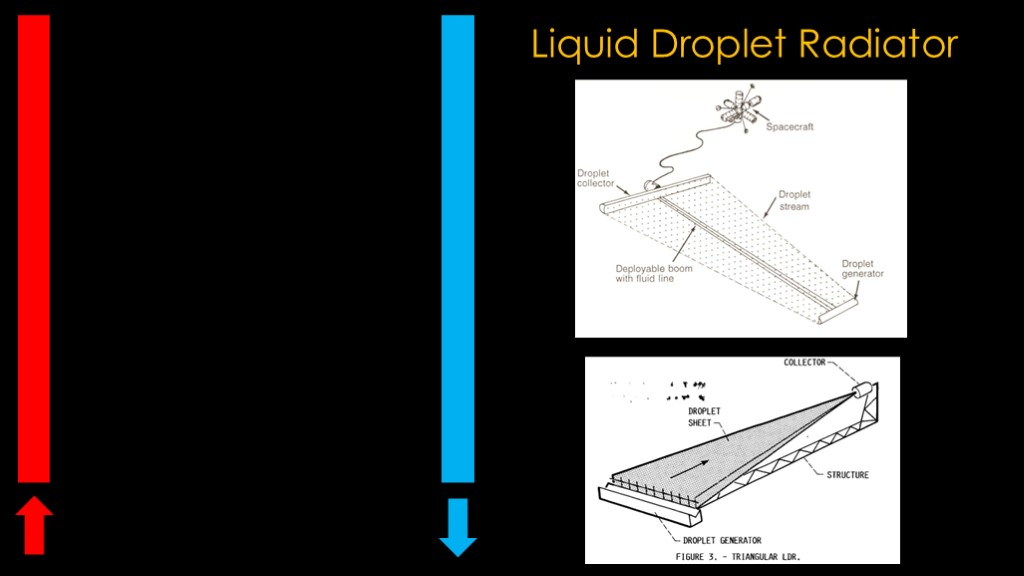
The obvious solution is to get rid of the troublesome tubes. Which sounds like a silly idea, but in microgravity the rules are different.
On the hot side, we place coolant emitters, and they spray the coolant into space in the direction of the collector , and the fluid cools as it travels. The droplets have a lot of surface area so they shed heat rapidly. This makes our radiator design small and light, which is good.
This is known as a liquid droplet radiator
There are a number of different designs.
I'm not sure how you keep the coolants from freezing on the input side if you don't have heat flow, but you might be able to go with a low temp coolant and heat up the emitter enough to make it work.
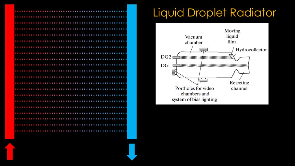
The Russians have run two experiments of this technology, one on Mir and one on ISS.
It kindof - sortof worked in that they could generate the droplets and could collect some of them in the right location, but there's a lot of technical development to make this practical.
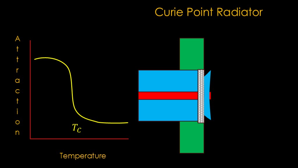
There is also a curie point radiator...
It exploits an interesting property of some materials. When they are cold, they are highly attracted to magnets, but when they are hot, they lose much of that attraction. The temperature where it changes is known as the Curie temperature.
We put a strong electromagnet right at the outside of our radiator, and run a coolant pipe through the middle with a catch basin around the pipe.
Take either particles or particles suspended in a liquid and spray them out into space. When they are hot, they are above the curie point and therefore travel mostly straight, but once they cool down below the Curie point, the magnetic attraction is greater and they are captured by the catch basin.
You might call this a magnetically assisted droplet radiator.
The problem with droplet radiators is that they would prefer to be stable in space rather than thrusting towards a destination.
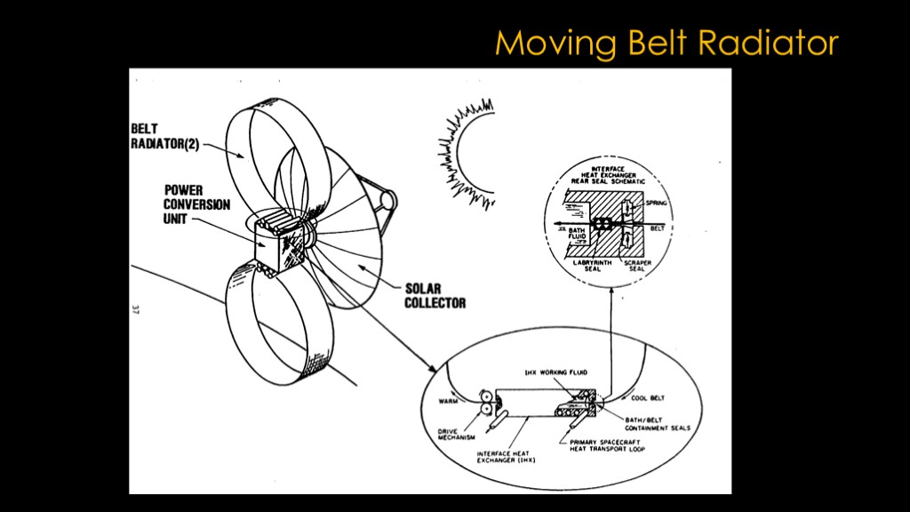
There's also the moving belt radiator, where the belt flows through a heat exchanger that has hot fluid in it, absorbs heat, and then radiates that heat off into space.
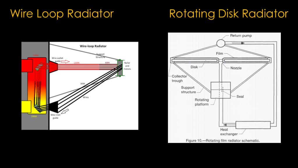
And the wire loop radiator and the rotating disk radiator.
These approaches might work but would need a significant amount of development.
Is there an option that is more likely to work.
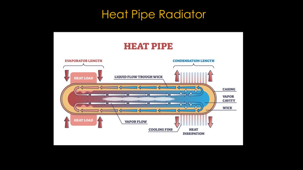
The proven approach is to use heat pipes.
In a heat pipe, we have a substance that is liquid at cooler temperatures, but when we add heat it vaporizes. The vapor travels to the other end of the heat pipe, where the heat is radiated away and the gas turns back into a liquid.
There is a lot to like about this system. Each heat pipe section is independent and therefore damage to one section doesn't compromise the whole radiator. It doesn't take any power to operate and with good design you should be able to shut it down and then restart it just by adding heat to the hot end. That will melt the coolant back to liquid and eventually turn it to gas.
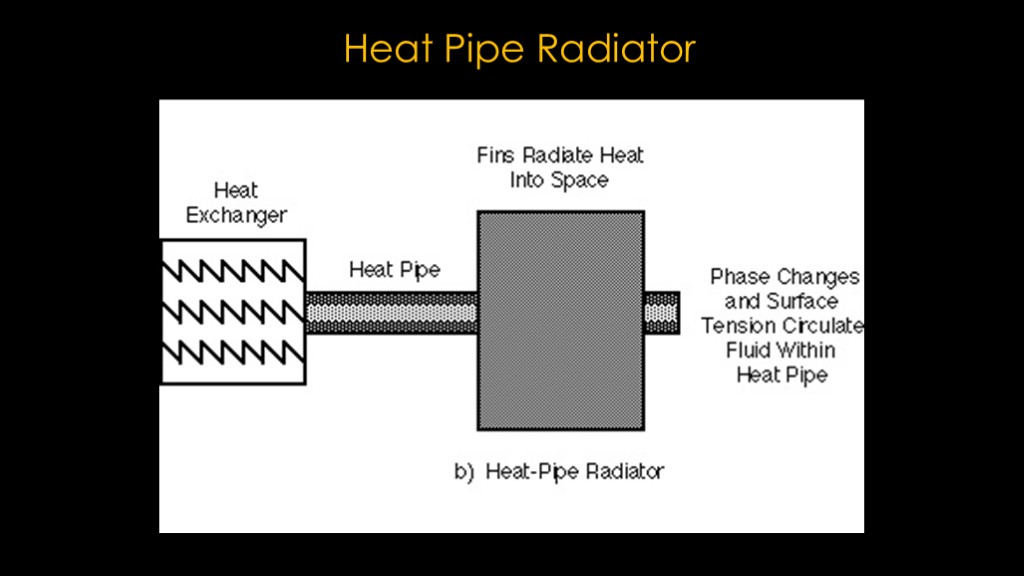
The actual designs use a heat pipe from a heat exchanger out to a finned radiator that will dissipate the heat.
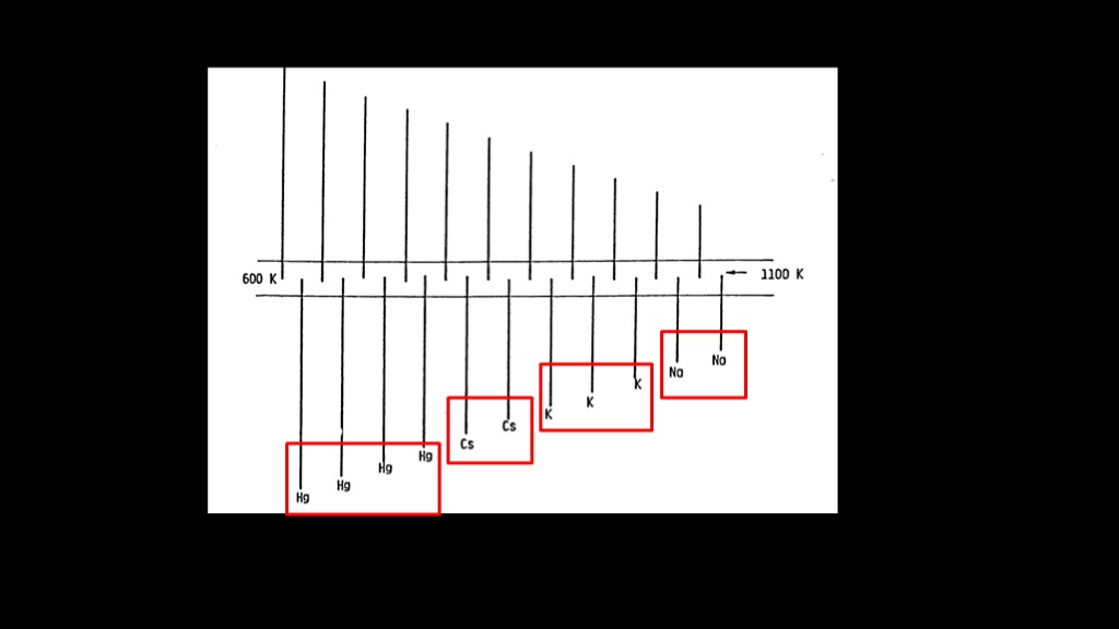
You can build heat pipes with different materials; in this design the hottest end uses sodium (highlight), then it moves to potassium, cesium, and finally Mercury.
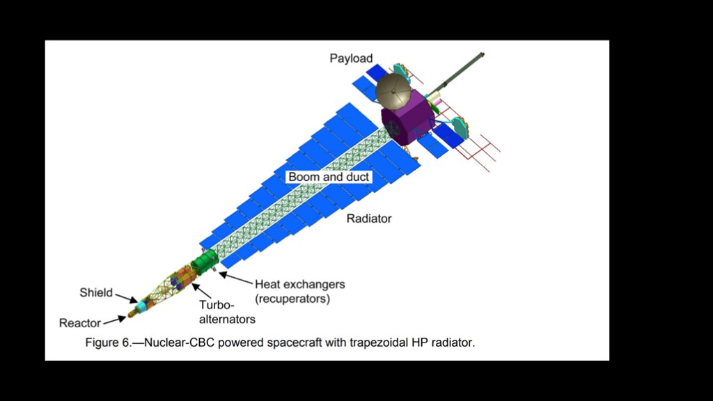
Here's what a proposed craft looks like.
Note that as the temperatures get lower towards the rear of the craft, the radiators get larger.
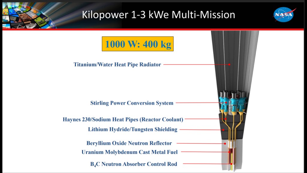
Heat pipes are not surprisingly used in NASA's kilopower reactor designed to provide power on the lunar surface.
Heat pipes are likely practical for getting rid of the reactor heat, but the downside is that they are heavy. That is why there is interest in alternate radiator designs.
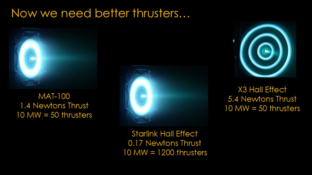
Now that we've thought about how to get 10 megawatts of electrical power, we need some thrusters that can use more energy to product more thrust.
Going back to the starlink thruster, we would need about 1200 thrusters to use 10 megawatts of power. Probably too many.
The X3 Hall Effect thruster puts out 30 times the thrust, and we would only need 50 thrusters to use 10 megawatts of power. Still too many.
The MAT-100 MPD thruster is about the same at 50 thrusters, but there are designs for higher power that haven't yet been built.
Can we do better?
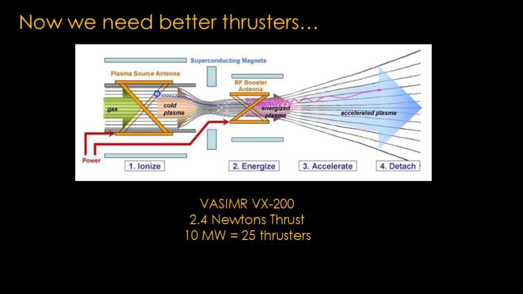
Another option is VASIMR. There are theoretical designs that can be high thrust, but current state of the art is a 200 kilowatt model, though it doesn't run at 200 kilowatts yet.
10 megawatts gives us 25 thrusters.
25 thrusters seems possible to me, but that's a lot of complexity and mass compared to a single chemical engine.
Scaling up these thrusters brings up another issue, and - remembering what Abe Hertzberg said - it's not surprising that it has to do with heat.
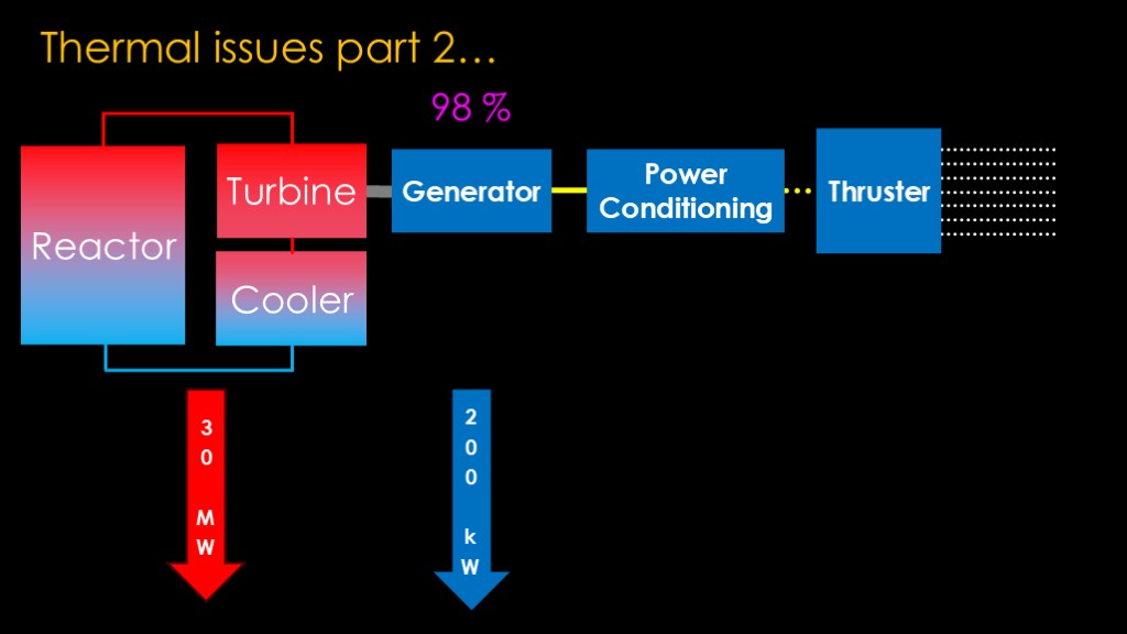
We already know that the reactor, turbine, and cooler are going to need to get rid of 30 megawatts of waste heat, but we also know that it's at a high temperature and that means the radiator area will be reasonable.
The turbine drives a generator to generate the power we need, and that feeds into a power conditioning system that converts the generator power into the power that the thrusters need, and that power goes into the thruster.
And then finally, the thruster takes that power and uses it to accelerate the propellant out to generate thrust.
Generators are fairly well understood, and good ones convert 95-98% of the mechanical power to electricity. That means we are losing at least 2% of 10 megawatts as heat, or 200 kilowatts. And it's a relatively cool heat - closer to the temperature electronics want than the temperature the reactor creates.
How efficient are the thrusters themselves?
This is a complex question, but I'm going start with the assumption that any losses in the thruster become heat. That's not right but it's close enough.
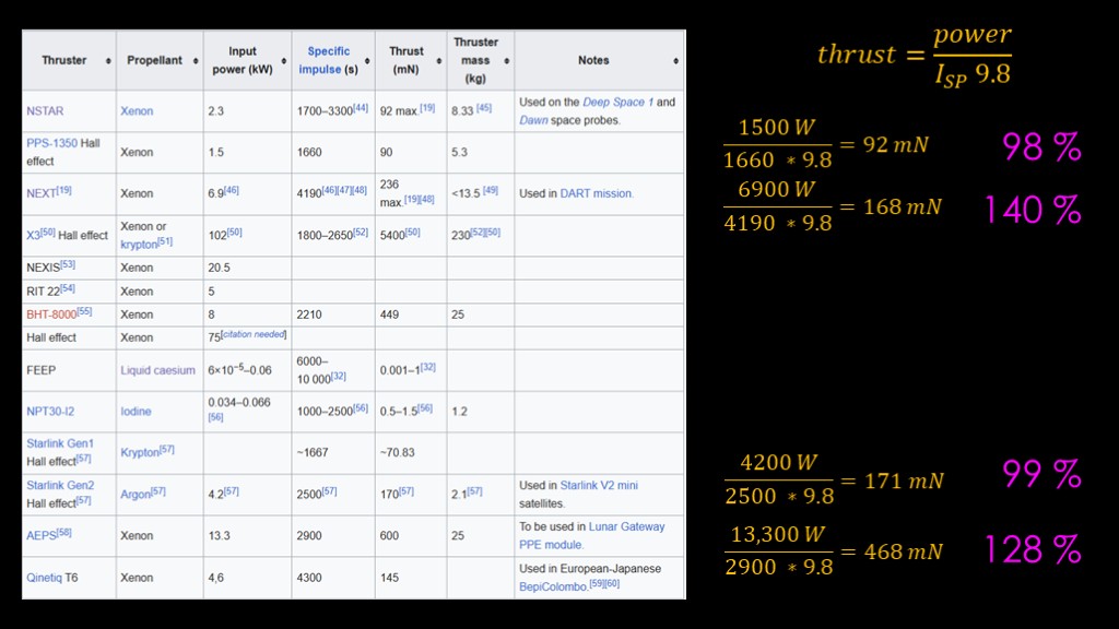
In trying to figure out thruster efficiency, I started with the Wikipedia ion thruster article because it has a nice table showing input power, specific impulse, and thrust.
That is very useful, as we know the thrust we get is equal to the power in watts divided by the specific impulse multiplied by 9.8. If we know the input power and the actual thrust, we can compute the efficiency.
We can try that with the starlink generation 2 thruster, and we get an answer of 171 millinewtons, pretty much an exact match.
If the thruster was 100% efficient, which it isn't. That means either the input power is not actually the input power or the thrust number is wrong.
If we do the same thing with the PSP-1350 thruster, we get a calculated thrust of 92 millinewtons, once again a pretty much exact match.
Neither of these are using input power.
The AEPS thruster uses 13.3 kilowatts of power and at a specific impulse of 2900, it generates 468 millinewtons of thrust. The stated thrust is 600 millinewtons, giving an efficiency of 128%.
If we look at the numbers for NEXT, the expected thrust is 168 millinewtons, and the thrust listed is 236 millinewtons, for an efficiency of 140%.
Some of these thrusters are just using the output power rather than the input power, which doesn't tell us anything about their efficiency.
Some of these thrusters are using numbers that clearly don't go with each other.
That didn't work out.
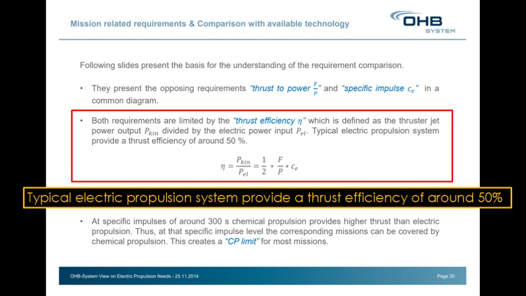
I found a 2014 presentation by OHB System, a German space system supplier who has the contract for ESA's Galileo navigation satellites.
They say that the typical electric propulsion system provides a thrust efficiency of around 50%.
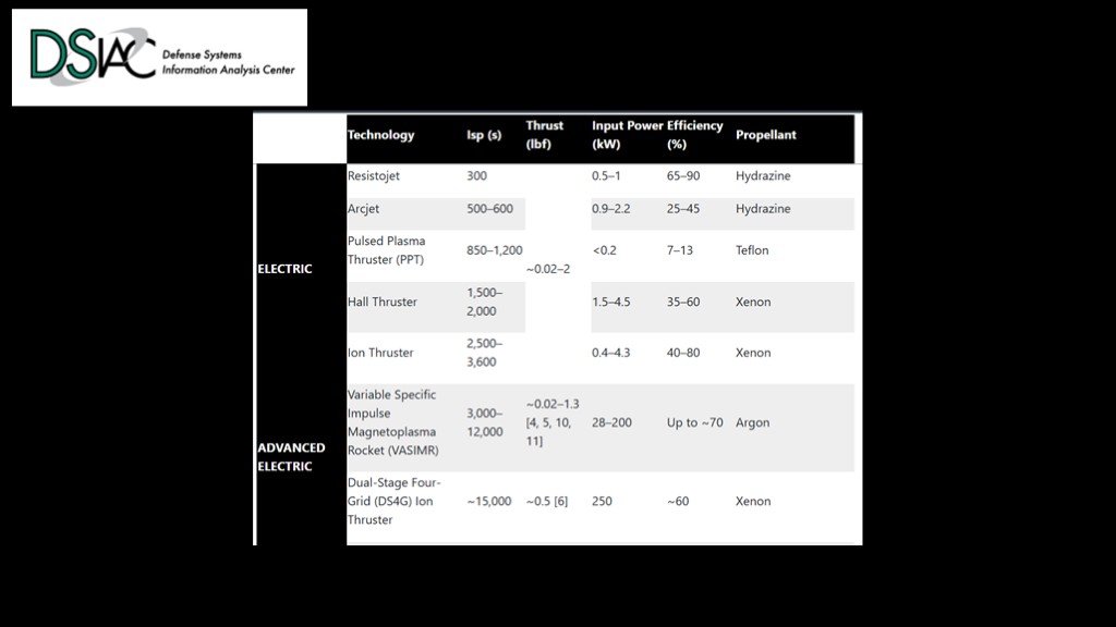
That roughly agrees with this chart from the defense systems information analysis center, which says 35-60% for hall thrusters, 40-80% for ion thrusters, and up to 70% for VASIMR thrusters.
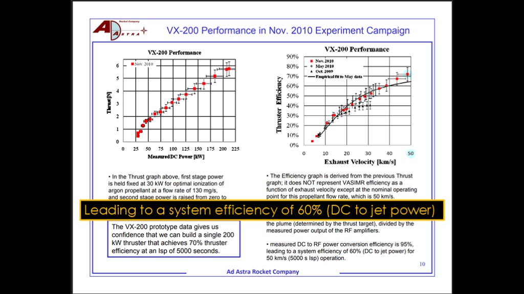
And this slide from ad astra talking about their VASIMR thruster prototype, which says they are getting a system efficiency of 60% from DC power in to jet power out.
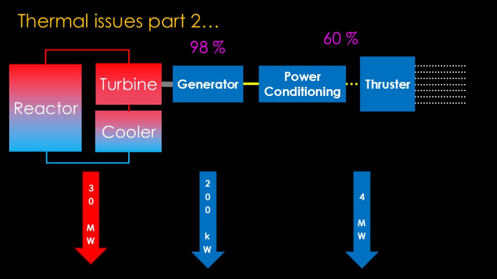
What this means is that you'll need some real numbers from the thruster you are going to use, but let's be generous and go with the 60% number achieved by VASIMR. That means our losses are 40% of our 10 MW input, or 4 megawatts...
Since we're looking at radiators we know that we need to know the temperature of those heat flows.
4 megawatts of relatively cool heat, because these thrusters use electronic components such as coils to generate them, and with VASIMR, they are superconducting coils, which have to be kept cold.
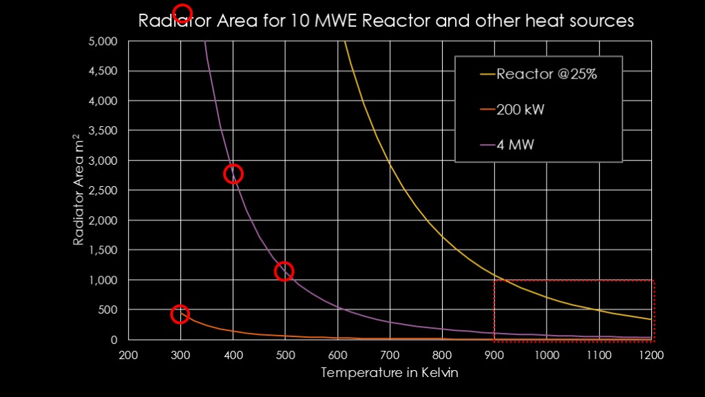
Our plan was to keep our reactor operating down in this area, with temperatures at 900 kelvin or above, so that we can keep our radiator area small.
But we have these other lower temperature heat loads. If we need to keep the generator at around 300 kelvin (27 centigrade or 80 Fahrenheit), we will need about 430 square meters of radiator.
But that's not the bad part, the bad part is the 4 megawatts that we need to get rid of from the thrusters.
If the thrusters will tolerate 500 kelvin (227 Celsius, 440 Fahrenheit), we can get away with 1300 square meters. At 400 kelvin, 2700 square meters. And at 300 kelvin, it's way off the top of the graph, at 8700 square meters.
Building the reactor to generate 10 megawatts of electrical power is the easy part from a thermal perspective - it's keeping the systems that use that 10 megawatts cool that is problematic.
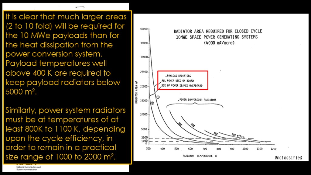
Back in 1988, NASA commissioned a study to look at big nuclear space power systems, and it includes a graph that looks very much like mine because I stole the idea from this study. The two payload curves on the left show the issue.
The text says the following...
It is clear that much larger areas (2 to 10 fold) will be required for the 10 MWe payloads than for the heat dissipation from the power conversion system. Payload temperatures well above 400 K are required to keep payload radiators below 5000 m2.
Similarly, power system radiators must be at temperatures of at least 800K to 1100 K, depending upon the cycle efficiency, in order to remain in a practical size range of 1000 to 2000 M2.
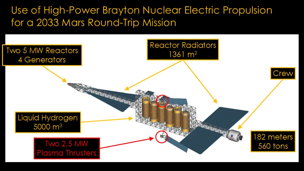
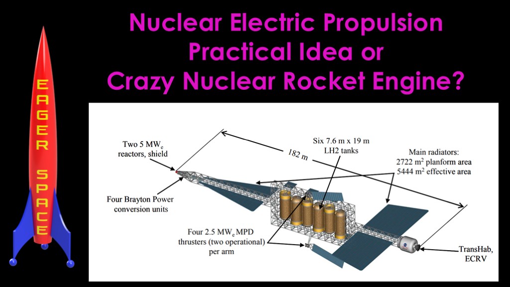
Here's a NASA design for a mars round trip mission.
Right out at the front there are two reactors and 4 generators that can produce a total of 10 megawatts of power.
There are two sets of reactor radiators with an area of 1360 square meters, with an active area double that as they can use both sides.
There are six liquid hydrogen tanks, each about half the size of a space shuttle external tank, containing a total of about 5000 cubic meters of liquid hydrogen.
These are placed at the center of the craft to keep the center of gravity constant over the mission, but that unfortunately means you need a way to get the hot reactor coolant 60 meters around the hydrogen storage to the back set of radiators. That exercise is left to the engineering team to figure out.
There's a crew module in the back
There are two thruster modules, each containing two 2.5 megawatt plasma thrusters, and with small radiators attached to them.
This behemoth is 182 meters long and masses 560 tons at launch.
That gets the crew to Mars and back home.
There's a second cargo vehicle roughly half the size that carries two moon landers (yes, that's what the paper says) for a rendezvous in Mars orbit.
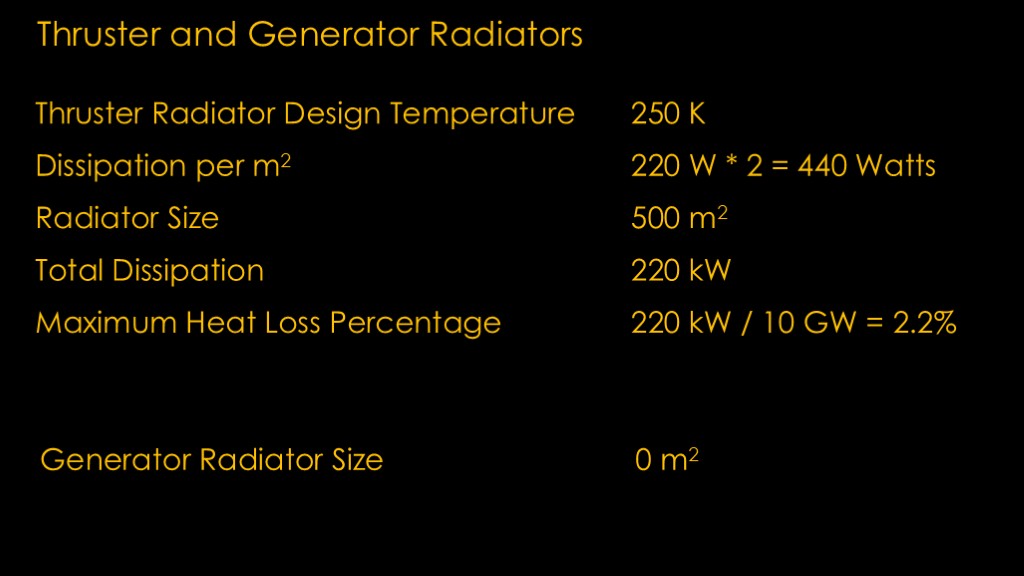
If you look at the thrusters they have these tiny little radiators attached to them.
The paper tells us that their design temperature for the thrust radiators is 250 kelvin, which means that each meter can dissipate 220 watts, or 440 watts if they are two-sided.
The radiator is 500 square meters in size, which means the radiator can dissipate 220 kilowatts.
It's a 10 gigawatt system, which means that the radiators can dissipate 220/10000 or 2.2% of the heat coming through. I don't know how efficient their power electronics and thruster design will be, but I'm pretty sure it's not going to be 97.8% efficient. That looks under designed.
As for the generator radiator, it doesn't exist. I don't think the generator is going to be happy being next to the turbine which is running at 1500 kelvin.
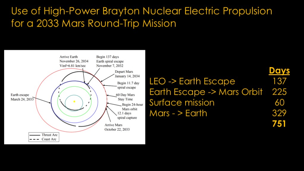
Here's the mission timing...
It takes about 360 days to get to mars orbit, 60 days for a mission, and then 329 days to get home, for about a 750 day total mission, a little over 2 years.
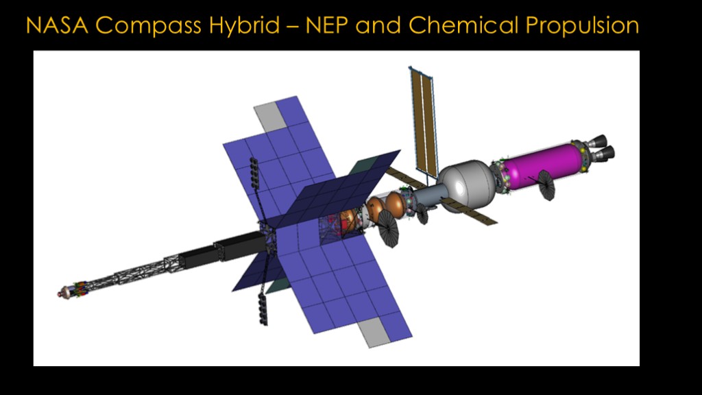
NASA has another design called Compass, which is uses a hybrid propulsion system = a small 1.5 megawatt nuclear reactor running ion thrusters and a large liquid oxygen liquid methane chemical stage.
The chemical stage is used for the parts that require a lot of delta v - getting to Mars injection, capturing into mars orbit, getting to earth injection.
I'm not going to get into the details of this proposal, but it's linked in the video description. The design includes a lot of detail.
Where does that leave us?
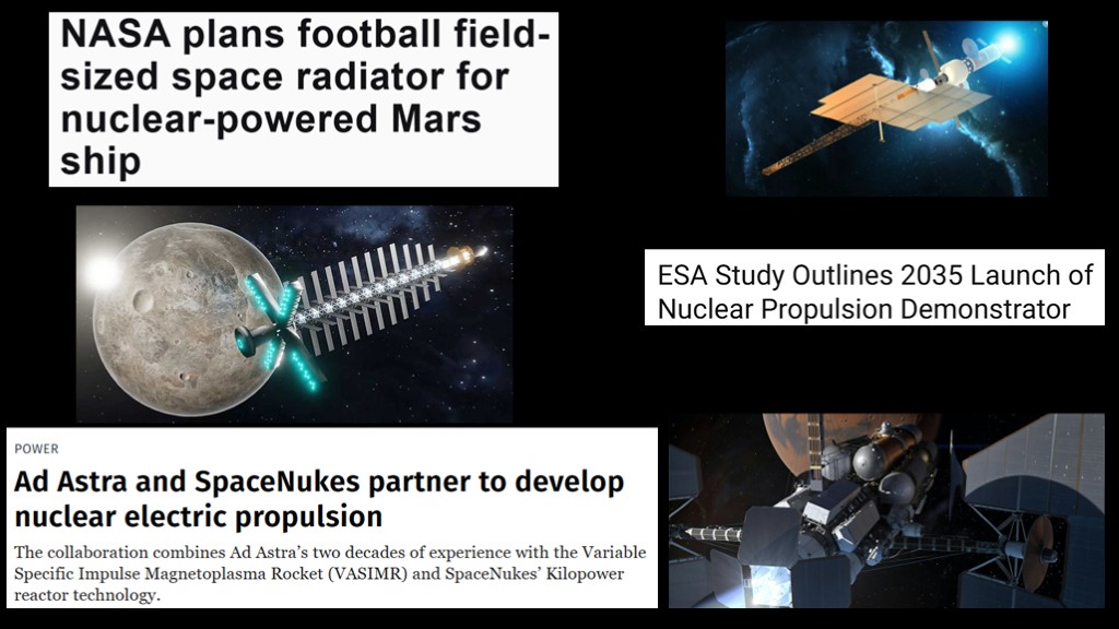
There's a lot of activity related to nuclear electric propulsion right now.
NASA has one called MARVL, the ESA has one called RocketRoll that I have been unable to find the final report on, and Ad Astra is working with SpaceNukes to hook their VASIMR engine up to a small reactor as a testbed.
But like nuclear thermal rocket engines, we don't have real designs actually flying.
I am hoping that somebody will build one so we can see a real-world model rather than a conceptual design, but at the current point I'm going to call this a crazy design.

The heat of the moment.
If you enjoyed this video, here's your song of the day...
https://www.youtube.com/watch?v=lCALGlGuVUA